The Rulbus Device Library supports the ISA Rulbus Interface as well as the EPP Rulbus Interface. At default the library assumes that the EPP Rulbus Interface is being used with the parallel port at address 0x378. If this assumption is not valid, the library must be informed what the proper interface type and address are. To this end the RULBUS environment variable can be defined as follows, here shown as shell commands:
set RULBUS=isa,0x200set RULBUS=epp,0x278
You can add ;nocheck to disable checking if the Rulbus Interface is present (EPP only). See also Setrulbus Utility.
Remember to configure the PC's parallel port to work in Enhanced Printer Port mode in the PC's BIOS, if you use the EPP Rulbus Interface.
In a program, software objects represent the physical Rulbus modules. These software objects are created from a Rulbus configuration file. This happens when the program references rulbus.dll for the first time and the DLL is loaded by the operating system.
Here is a small Rulbus device configuration file.
# rulbus-small.conf - example rulbus device configuration file.

rack "top"
{
    address = 0

    rb8509_adc12 "adc"
    rb8510_dac12 "dac-ch0" { address = 0xD0 }
    rb8510_dac12 "dac-ch1" { address = 0xD2; bipolar = false; volt_per_bit = 1.25m }
}

rack "bottom"
{
   address = 1

   // still empty
}
And here is a longer configuration file.
The configuration file defines racks that contain modules (cards). Besides card declarations, a rack declaration usually contains an address specification (See secondary address).
The card declarations specify the type of the card and the name by which it is referenced from the program. All card types can specify the address property and several card types can specify other properties, like bipolar for card type rb8510_dac12. The available properties and their default values are given in the section Default configuration in the reference manual for the various card types.
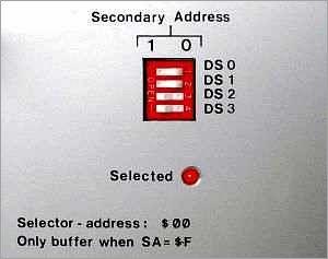
When more than one rack is used, each rack must have a unique address. The address of a rack is defined at its rear side via a 4-bit DIP-switch, so that rack addresses fall in the range 0--15.
Address 15 has a special meaning: the rack is always selected or active. In this case it must be the only rack connected to the computer--Rulbus interface.
If a rack has an address in the range 0--14, the rack must be specifically selected by a program before the cards it contains can be accessed. Note that the Rulbus Device Library takes care of this.
So with rack addressing, the range of available addresses is extended to 15 times 254, or 3810.
The figure above shows a rack with secondary address 3: binary 0011, 0*2^3 + 0*2^2 + 1*2^1 + 1*2^0 .
Note that the Rulbus Interface cannot be specified in the Rulbus device configuration file. The rationale behind this is, that the Rulbus Interface is related to the computer, whereas the items in the Rulbus device configuration file are related to the application. When a PC is replaced by another one, the application and the Rulbus device configuration file should move to the new computer, but not the Rulbus Interface specification.
The path of the configuration file to read is determined as follows:
RULBUS_CONFIG_FILE, or
You can set the environment variable RULBUS_CONFIG_FILE in a command shell temporarily as follows:
set RULBUS_CONFIG_FILE=M:\myexperiment\etc\rulbus.conf
For Windows 95 types of operating system (Windows 95/98/me) the RULBUS and RULBUS_CONFIG_FILE environment variables must be recorded in autoexec.bat by editing it. For Windows NT types of operating system (Windows NT/2000/XP) they must be recorded in the registry, for example via System Properties, Environment.
To make it easy to select the proper Rulbus Interface and to define the path to the Rulbus configuration file on either operating system type, a small GUI program has been made: setrulbus.exe.
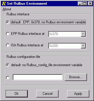
Open setrulbus via Start | Rulbus Device Library | Tools | Set Rulbus Environment. Program setrulbus is located in the programs subdirectory of the Rulbus Device Library installation directory.
| previous | top | next |